
CONCEPTOS & DIFERENCIAS CON CAD
UTM es un sistema de coordenadas ampliamente utilizado, sobre todo en ingeniería y arquitectura, para posicionar geográficamente los proyectos. A diferencia del sistema de coordenadas geográficas, expresadas en longitud y latitud, las magnitudes en el sistema UTM se expresan en metros.
Para saber más sobre este sistema de coordenadas, te recomiendo recurrir a los enlaces de interés que dejo en la sección inferior de este artículo.
UTM is a widely used coordinate system, especially in engineering and architecture, to geographically position projects. Unlike the geographic coordinate system, expressed in longitude and latitude, magnitudes in the UTM system are expressed in meters.
To learn more about this coordinate system, I recommend you use the links of interest that I leave in the lower section of this article.
UTM REVIT VS UTM CAD – DIFERENCIAS ENTRE POSICIONAMIENTO
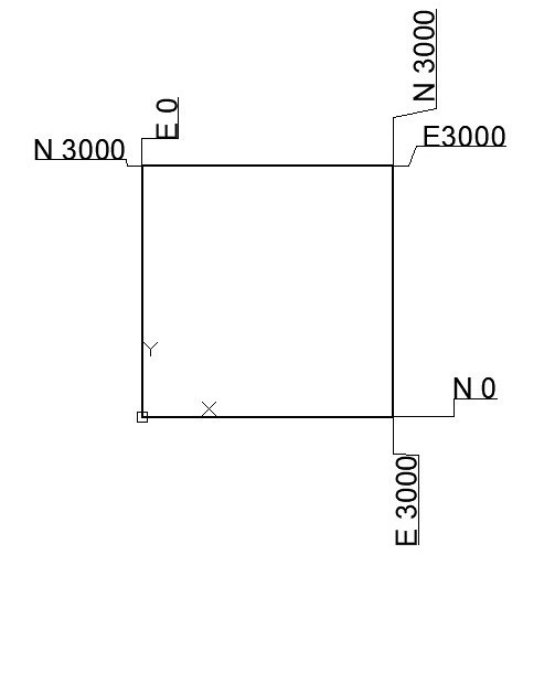
Las coordenadas UTM de un dibujo en CAD vienen definidas por la posición del proyecto respecto al origen de coordenadas del sistema universal (SCU). El origen del SCU es el origen del archivo, y además marca el 0.0.0 del sistema de coordenadas topográficas.
Si queremos ubicar el dibujo de CAD en coordenadas UTM, tenemos que desplazar el dibujo hasta hacer coincidir la posición del origen del SCU con el 0.0 UTM. De tal forma que las coordenadas de todos los elementos dibujados coincidan con la posición que tendrían en el mundo real.
The UTM coordinates of a CAD drawing are defined by the position of the project with respect to the origin of coordinates of the universal system (UCS). The origin of the UCS is the origin of the file, and also marks the 0.0.0 of the topographic coordinate system.
If we want to locate the CAD drawing in UTM coordinates, we have to move the drawing until the position of the WCS origin coincides with 0.0 UTM. In such a way that the coordinates of all the drawn elements coincide with the position they would have in the real world.
Dibujo CAD sin referenciar en coordenadas UTM. Origen del SCU no define origen UTM. 
Dibujo CAD referenciado en coordenadas UTM. Origen del SCU define origen UTM tras mover modelo.
En Revit el entorno de trabajo no es infinito como ocurre en AutoCAD. Es un lienzo finito cuyo limite estable se encuentra a 33 km respecto al origen del archivo, denominado Internal origin u origen interno (IO) en Revit: (Categoría Emplazamiento > Origen Interno).
Es por ello que el origen del archivo no define el sistema de coordenadas UTM como ocurre en AutoCAD. En su lugar el origen del sistema de coordenadas UTM lo define el survey point o punto de reconocimiento (SP). Dicho punto se puede mover y se le pueden asignar coordenadas (Para que siga definiendo el origen UTM aun sin estar situado específicamente en el 0.0).
In Revit the work environment is not infinite as it is in AutoCAD. It is a finite canvas whose stable limit is 33 km from the origin of the file, called Internal origin or internal origin (IO) in Revit: (Site Category > Internal Origin).
That is why the origin of the file does not define the UTM coordinate system as it does in AutoCAD. Instead the origin of the UTM coordinate system is defined by the survey point or reconnaissance point (SP). This point can be moved and coordinates can be assigned (so that it continues to define the UTM origin even without being specifically located at 0.0).
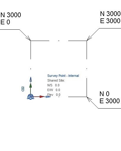
Dibujo REVIT sin referenciar en coordenadas UTM. Survey Point ubicado en origen interno del archivo. 
Dibujo REVIT referenciado en coordenadas UTM. Survey Point desplazado respecto al origen interno del archivo.

(IO) INTERNAL ORIGIN – ORIGEN INTERNO
Este punto, (Origen interno) no se puede mover. Define el origen del archivo de Revit y el límite sin problemas del archivo (33 km). No define coordenadas UTM, ni tampoco coordenadas de proyecto. Está definido con un par de flechas.
Nota: Es recomendable que este punto tenga una posición conocida y controlada desde el principio del modelado. Ya que no se puede mover a posteriori y muchos programas tienen la opción de usarlo como referencia.
This point, (Internal Origin) cannot be moved. Defines the origin of the Revit file and the smooth boundary of the file (33 km). It does not define UTM coordinates, nor project coordinates. It is defined with a pair of arrows.
Note: It is recommended that this point have a known and controlled position from the beginning of the modeling. Since it cannot be moved later and many programs have the option to use it as a reference.
(SP) SURVEY POINT – PUNTO DE RECONOCIMIENTO
Este punto es el origen de coordenadas topográficas que nos permite ubicar el proyecto en el mundo. Es el equivalente al UCS de CAD. Con una diferencia fundamental, se puede mover y se le pueden asignar coordenadas.
VARIOS EMPLAZAMIENTOS, MISMO ARCHIVO REVIT
Además, este punto puede poseer varios emplazamientos configurados dentro de un mismo modelo de Revit. De tal forma a como funcionan los SCP en AutoCAD. Aunque solamente uno podrá estar activo, y es lo que definirá su sistema de coordenadas compartidas. Se puede por ejemplo tener configurado un sistema de coordenadas global, y tener otro que configure el sistema de coordenadas local. Para poder usar el Base Point como punto de replanteo de cada modelo particular de Revit.
This point is the origin of topographic coordinates that allows us to locate the project in the world. It is the equivalent of CAD’s UCS. With one fundamental difference, it can be moved and coordinates can be assigned to it.
MULTIPLE SITES, SAME REVIT FILE
Furthermore, this point can have multiple sites configured within the same Revit model, similar to how UCSs work in AutoCAD. However, only one can be active at a time, and this defines its shared coordinate system. For example, you can have a global coordinate system configured and another that defines the local coordinate system. This allows you to use the Base Point as a layout point for each individual Revit model.

El SURVEY POINT (SP) tenga un origen 0.0 que nos marque el origen UTM. 
El origen 0.0 del SURVEY POINT (SP) sigue estando en la misma posición aunque el punto tenga unas coordenadas definidas.
Nota: Es recomendable tener este punto ubicado en algún lugar conocido y medible del proyecto. Normalmente suele asignarse a un punto topográfico de la parcela del proyecto dado por el técnico responsable. Esto nos permite comprobar rápidamente entre diferentes edificios de un mismo proyecto si todos tienen asignado el mismo SP, y por tanto si todos están ubicados geográficamente de forma correcta.
Note: It is recommended to have this point located somewhere known and measurable in the project. Normally it is usually assigned to a topographic point of the project plot given by the responsible technician. This allows us to quickly check between different buildings of the same project if they all have the same SP assigned, and therefore if they are all correctly geographically located.

(BP) BASE POINT – PUNTO BASE
En Revit, el sistema local de coordenadas de cada modelo Revit lo define el Base Point (BP). El BP es el punto de replanteo de cada uno de los modelos Revit.
Sus coordenadas hacen referencia a la posición que tiene en el mundo respecto al (SP) SURVEY POINT. La posición de este punto no define las coordenadas UTM del proyecto.
Hay que entender que el BP forma parte del propio proyecto como un elemento más. Si modificamos la posición UTM del proyecto modificamos también las coordenadas del BP. Como ocurriría con cualquier otro elemento.
In Revit, the local coordinate system is defined by the Base Point (BP). The BP is the stakeout point of the project.
Its coordinates refer to its position in the world with respect to the (SP) SURVEY POINT. The position of this point does not define the UTM coordinates of the project.
It must be understood that the BP is part of the project itself as one more element. If we modify the UTM position of the project, we also modify the coordinates of the BP. Just like any other item.
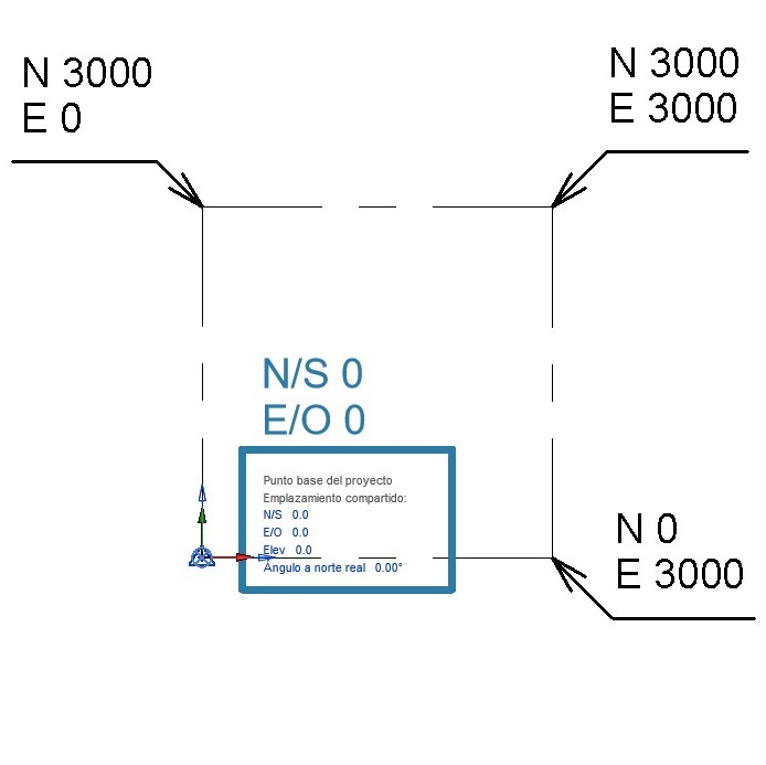
Al abrir un archivo, el BP está ubicado junto al SP. Por tanto, sus coordenadas son 0.0 
Las coordenadas del BP dependen de la distancia de éste respecto al punto de reconocimiento SP.
ENLACES DE INTERÉS / INTEREST LINKS:
- DISTRITO BIM. ( 29/07/2021) – COORDENADAS COMPARTIDAS – ¿Llevas años trabajando en Revit pero el tema de las coordenadas compartidas se te rebela? ¡Se acabó! Te lo vamos a contar como nunca antes te lo habían contado.– Recuperado el 12/07/2022 de https://distritobim.com/llevas-anos-trabajando-con-revit-pero-el-tema-de-las-coordenadas-compartidas-se-te-revela-se-acabo-te-lo-vamos-a-contar-como-nunca-antes-te-lo-habian-contado/
